


Views: 0 Author: Site Editor Publish Time: 2026-10-27 Origin: Site


Estimating the exact force needed to bend metal dictates the success of your fabrication run. Guessing the required tonnage leads to stalled rams, ruined material, and rejected parts. Oversizing your equipment wastes capital and accelerates tooling wear. You need to match material properties, tooling geometry, and part length to the correct machine capacity using hard math. Relying on shop floor intuition often damages expensive dies or permanently deflects the machine frame. A standardized approach to press brake tonnage calculation guarantees safe operations. It protects your tooling investments and guides accurate procurement decisions. By understanding the interaction between material tensile strength, thickness, and V-die openings, you can optimize bending processes and select the exact machinery required for your production demands.
Formulaic Precision: Accurate tonnage requires calculating the relationship between material thickness, tensile strength, bend length, and V-die opening.
Bending Method Multipliers: Air bending, bottoming, and coining require drastically different force profiles; bottoming can require up to 5x the tonnage of air bending.
Concentrated Load Limits: Total machine tonnage is secondary to the maximum allowable tonnage per foot/meter—exceeding this causes permanent ram deflection and tooling fracture.
Procurement Alignment: Calculating required tonnage is the foundational step in evaluating and shortlisting a CNC hydraulic press brake for your facility.
Relying on old tonnage charts or broad estimates fails in modern manufacturing. High-tolerance fabrication demands exact force application. You must maintain precise bend angles across varying material batches. When operators guess the required force, they risk applying too much pressure. This coins the material and damages the die shoulder. Applying too little pressure results in severe under-bending and massive material springback.
Engineers globally use a core mathematical equation: Tonnage = (Length × Thickness² × Tensile Strength) / (V-Die Opening × Constant). This formula forms the bedrock of all force estimations. Thickness has an exponential impact on force. Length has a linear impact. Understanding this equation lets you manipulate variables safely when standard tooling is unavailable.
The constant in the formula changes based on your measurement system. When calculating in inches and US tons, you use a specific imperial constant to balance the equation. Metric calculations measure thickness and length in millimeters and force in kilonewtons. They require a different baseline divisor. Mixing these units without proper conversion causes catastrophic tooling failure.
Modern digital calculators and CNC software act as verification tools. They cross-check manual engineering calculations to prevent human error. You do this before loading the first piece of metal into the machine. Manual math provides the foundational understanding. Digital controllers simulate the bend sequence. They instantly calculate the required tonnage for each step and flag any operation exceeding safe working limits.
Several variables dictate the final force requirement on the shop floor. The mechanics of the V-die play a massive role. The material bridges the V-die opening, and the punch pushes down, creating a lever arm. The shorter the lever arm, which happens when using a narrow V-die, the more force required to bend the metal.
Material Thickness: Both gauge and decimal thickness exponentially impact the required force. Because thickness is squared in the formula, doubling the material thickness quadruples the required tonnage.
Bend Length: There is a direct linear relationship between the length of the bend and total tonnage. A 10-foot bend requires exactly twice the force of a 5-foot bend in the same material.
V-Die Opening: This features an inverse relationship. Wider V-dies reduce the required tonnage by increasing the leverage on the material. They simultaneously increase the internal bend radius.
Bending Angle and Internal Radius: The target bending angle shifts the tonnage curve. Standard 90-degree bends differ from acute or obtuse angles. Tighter internal radii demand significantly higher concentrated force.
Variable |
Impact on Tonnage |
Practical Example |
|---|---|---|
Thickness |
Exponential (Squared) |
Moving from 0.125" to 0.250" plate increases required force by 4x. |
Length |
Linear |
Bending 120 inches takes twice the force of bending 60 inches. |
V-Die Opening |
Inverse |
Increasing die width from 1" to 2" cuts the required tonnage in half. |
Tensile Strength |
Linear Multiplier |
Switching from mild steel to stainless increases force by roughly 1.5x. |
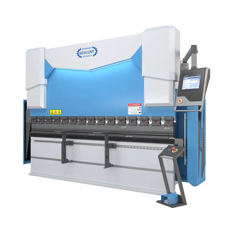
Establishing a baseline is necessary for any comparative calculation. In steel sheet metal bending, mild steel with a typical tensile strength of 60,000 PSI serves as the standard baseline. All standard tooling charts, slide rules, and basic formulas assume this material profile. If a chart states that bending 1/4-inch plate over a 2-inch V-die requires 15.3 tons per foot, that figure applies strictly to standard mild steel.
When forming different alloys, you must apply specific material multipliers to the baseline tonnage. Failing to apply these multipliers results in severe under-calculation. This leads to stalled rams and incomplete bends on the shop floor. You must understand the difference between yield strength and ultimate tensile strength. Tensile strength dictates the point at which the material fractures, and it serves as the primary metric for calculating bending force.
Stainless Steel: Requires a multiplier of approximately 1.5x to 1.7x. This increase happens due to its higher yield strength and tendency for work hardening during the bending process. As the punch pushes into the stainless steel, the material physically hardens at the bend line. You need progressive force to complete the angle.
Aluminum: Generally requires a multiplier of 0.5x to 0.8x. The exact factor depends heavily on the specific grade and temper of the aluminum alloy being formed. Soft alloys like 3003 need very little force. Aircraft-grade aluminum like 7075-T6 approaches mild steel requirements and cracks easily if the V-die is too narrow.
High-Strength Steels: Materials like AR400, AR500, or Domex demand exact mill certificates for accurate estimation. These alloys can require double or triple the baseline force. Bending a 1/2-inch plate of AR400 requires specialized heavy-duty tooling and a machine with exceptionally high concentrated load limits.
Let's look at how these multipliers play out in a real-world fabrication scenario. If your baseline calculation for a mild steel part dictates 50 tons of force, swapping that exact same part profile to 304 stainless steel instantly bumps your requirement to 75 or 85 tons. If you fail to adjust your machine settings or verify your tooling capacity for that jump, you will likely fracture the die or stall the hydraulics mid-stroke.
Material Type |
Tensile Strength (Approx) |
Tonnage Multiplier |
|---|---|---|
Mild Steel (Baseline) |
60,000 PSI |
1.0x |
Stainless Steel (304/316) |
85,000 - 90,000 PSI |
1.5x - 1.7x |
Soft Aluminum (3003) |
20,000 - 30,000 PSI |
0.5x |
Hard Aluminum (6061-T6) |
40,000 - 45,000 PSI |
0.8x |
High-Strength Steel (AR400) |
100,000+ PSI |
2.0x+ (Check Mill Specs) |
The chosen bending methodology fundamentally alters the force required to shape the metal. Different solution categories apply distinct mechanical pressures to the workpiece. This changes how the material yields and how the machine absorbs the reactive force. Punch tip radius also plays a role. A sharp punch requires less force but penetrates the material, causing a crease. A large radius punch requires more force to wrap the material around it.
Air bending remains the industry standard across modern fabrication shops. It requires the least amount of tonnage. The material only contacts the tooling at three points: the punch tip and the two upper shoulders of the V-die. The V-die width directly dictates the force. Wider dies increase leverage and drop the tonnage requirement. Because the punch does not push the material all the way to the bottom of the die, operators can form multiple angles with the same tooling simply by controlling the ram depth.
Bottom bending, or bottoming, forces the material fully into the die angle. This method requires 3x to 5x more tonnage than air bending. The punch presses the sheet metal against the inner walls of the V-die to achieve a more exact angle and reduce springback. It provides excellent repeatability for specific angles. However, the massive force required causes rapid tooling wear. It also limits the thickness of material a given machine can process.
Coining involves extreme tonnage requirements. It often takes up to 10x the force of air bending. The goal is to stamp the punch tip directly into the neutral axis of the material. This permanently thins the metal at the bend line and completely eliminates springback. Modern facilities rarely use this method. A modern CNC hydraulic press brake achieves high precision through advanced software and air bending. This eliminates the need for destructive, high-tonnage force.
Specialty tooling introduces unique considerations. Offset dies and hemming dies require careful force planning to prevent tooling explosion. For offset dies, follow a strict 4-step calculation process:
Determine the base tonnage from standard air bending charts based on the material thickness.
Apply the specific material multiplier based on the alloy being formed.
Account for the dual bend geometry. Since an offset die forms two bends simultaneously, it effectively doubles the required force.
Calculate the total required tonnage by multiplying these factors together and verifying against the die's maximum load rating.
Urethane tooling also affects force distribution. Urethane acts as a solid fluid. It wraps around the punch, requiring modified tonnage calculations. These typically exceed standard air bending forces to achieve the same profile. The upward resistance of the urethane pad means the machine must push harder to displace the material.
Translating maximum calculated tonnage into actual machine specifications is a major engineering task. You must use your maximum calculated force to determine the required capacity of a new sheet metal bending machine. Buying a machine that exactly matches your maximum calculation leaves no room for error. It ignores material inconsistency and future business expansion.
Always add a 20% to 30% safety margin to your maximum calculated tonnage. Running a machine at maximum hydraulic pressure continuously degrades pump efficiency. It overheats hydraulic fluid and shortens valve life. A buffer prevents premature component failure. It provides flexibility for future, slightly thicker material batches. If your calculations show you need 100 tons to bend your thickest part, you should specify a 120-ton or 130-ton machine.
Concentrated load capacity is a heavily overlooked metric. We express this as tonnage per foot or meter. Bending a thick, short part can easily exceed the ram's localized load limit even if the total machine tonnage is sufficient. If a 200-ton machine has a limit of 20 tons per foot, applying 50 tons over a 6-inch area will permanently deform the ram. This creates a permanent bow that ruins all future long bends. Operators must calculate both total tonnage and tonnage per foot for every heavy-plate setup.
High-tonnage applications inevitably cause ram and bed deflection. As the hydraulic cylinders push down on the ends of the ram, the center tends to bow upward slightly. The lower bed bows downward. This causes the punch to penetrate less in the center of the part. You get a wider angle in the middle than at the ends. CNC hydraulic crowning systems counteract this deflection by pushing the center of the bed upward. These crowning systems use a series of hydraulic cylinders built into the lower bed. The CNC calculates the exact amount of deflection based on the tonnage and material length, and automatically pushes the center of the bed upward to keep the tooling perfectly parallel under load.
Engineering and operational failures related to tonnage estimation happen frequently when operators ignore variables. One major implementation risk is ignoring the internal radius. Forcing a tight internal radius on thick material spikes tonnage requirements exponentially. It severely risks tooling fracture. As a general rule, the internal radius should be roughly equal to the material thickness. Attempting to force a sharp punch into thick plate requires massive force. It often cracks the outside of the bend.
Another frequent error involves tooling load limits. Calculating hydraulic press brake tonnage without verifying the maximum load rating of the punch and die is dangerous. Tooling is usually rated in maximum tons per meter or foot. If the machine can deliver 100 tons per meter but the die is only rated for 50 tons per meter, the die will split under pressure. This destroys expensive tooling and creates a severe safety hazard from flying metal shrapnel. Always verify the tooling load limit against your calculated tonnage per foot.
Material springback also introduces calculation risks. High-tensile materials resist deformation. They try to return to their original flat state after the ram retracts. Operators must over-bend these materials to compensate. Failing to account for the extra force required to drive the punch deeper into the die for over-bending results in stalled machines. You get inaccurate final angles. The calculation must account for the deeper penetration required to achieve the final resting angle.
Many shops also fail to account for grain direction in the sheet metal. Bending parallel to the grain requires slightly less tonnage but drastically increases the chance of cracking. Bending perpendicular to the grain requires more force but yields a stronger, cleaner bend. Your tonnage calculations should always assume the higher force requirement of bending perpendicular to the grain to ensure you have adequate machine capacity.
Off-center loading presents another massive risk. Bending short, heavy pieces on the extreme ends of the press brake bed causes uneven loading. This damages the ram guides and puts unequal stress on the hydraulic cylinders. Always center heavy loads to distribute the tonnage evenly across the machine frame.
Choosing the right equipment partner separates a commodity machine from a high-performance metal forming hydraulic press. Several value-influencing factors dictate long-term reliability and precision on the shop floor.
Frame rigidity and machining quality are paramount. The weight and thermal stress relief of the machine frame matter just as much as the stated hydraulic tonnage. A heavy, properly stress-relieved frame resists deflection. It maintains tooling alignment under heavy loads. High-quality manufacturers use thick steel plates welded into a rigid structure. After welding, the entire frame must undergo thermal stress relief in a massive oven. This process eliminates the internal stresses created during welding. Manufacturers who cut corners on steel plate thickness produce machines that twist and warp under maximum tonnage. This makes precision bending impossible regardless of the CNC system used.
Evaluate the hydraulic system architecture carefully. Look for an industrial press brake manufacturer that utilizes proportional valve technology, precise dual-cylinder synchronization, and energy-efficient hybrid systems. Proportional valves ensure that tonnage is delivered smoothly and accurately. They allow the CNC to adjust the ram position within microns. Dual-cylinder synchronization ensures the ram remains perfectly parallel to the bed during the entire stroke. Optical linear scales read the ram position to within 0.01mm, feeding data back to the CNC to maintain perfect alignment.
Consider the trade-off between buying a massively oversized machine versus a correctly sized machine. An oversized machine carries high upfront capital costs. It consumes more floor space and electricity. It also moves slower, reducing overall throughput for lighter parts. Conversely, a correctly sized machine equipped with precision CNC crowning and high-quality tooling delivers superior part accuracy without wasted capacity. Focus on matching the machine's capabilities to your actual calculated requirements, plus the recommended safety margin.
Take the following next steps to finalize your production planning and equipment procurement:
Compile a comprehensive list of all materials, thicknesses, and bend lengths currently processed in your facility to identify your worst-case bending scenario.
Calculate the required tonnage for your most demanding parts using the standard formula, and apply a 20% to 30% safety margin to determine your target machine capacity.
Verify the maximum load limits of your existing punch and die inventory against your new calculations to ensure your tooling can handle the expected force.
Consult with an applications engineer to run test bends and verify your mathematical models with real-world material.
A: The standard formula is: Tonnage = (Length × Thickness² × Tensile Strength) / (V-Die Opening × Constant). The constant varies based on your measurement system. Imperial calculations use a specific divisor for inches and US tons. Metric calculations use a different constant for millimeters and kilonewtons.
A: There is an inverse relationship between V-die width and required force. A wider V-die increases the mechanical leverage on the sheet metal. This significantly reduces the required bending tonnage. However, using a wider die also results in a larger internal bend radius on the finished part.
A: When bending stainless steel, you must apply a multiplier of 1.5x to 1.7x to the baseline mild steel tonnage. This accounts for the higher yield strength and the material's tendency to work-harden as it deforms during the bending process.
A: Tonnage per foot dictates the concentrated load limit of the machine's ram. Bending a short, thick part can exceed this localized limit even if the total machine capacity is high. Exceeding the concentrated load limit causes permanent ram deformation and destroys tooling.
A: You should add a 20% to 30% safety margin to your absolute maximum calculated tonnage. This buffer prevents the machine from running continuously at peak hydraulic pressure. It extends the lifespan of the pumps, valves, and seals.
A: Yes, bottom bending requires significantly more force. Because the punch forces the sheet metal completely into the V-die to match the exact die angle, bottoming typically requires 3 to 5 times more tonnage than standard air bending.
A: Calculating offset die tonnage involves a 4-step method. First, determine the base tonnage from a standard air bending chart. Second, apply the specific material multiplier. Third, account for the dual bend geometry, which effectively doubles the force requirement. Finally, multiply these factors for the total calculation.


