


Views: 0 Author: Site Editor Publish Time: 2026-10-14 Origin: Site


Manual sheet metal stamping pushes the physical limits of traditional manufacturing floors. Relying on human operators introduces severe ergonomic strain, inevitable fatigue, and significant safety hazards. These human factors create inconsistent cycle times that throttle overall plant throughput. Scaling production and achieving simultaneous part loading and unloading across multiple die stations is nearly impossible without risking catastrophic press crashes or relying heavily on manual intervention. Transitioning from manual handling to a deterministic, robot-tended architecture establishes a highly predictable production baseline. This shift redirects focus from managing manual labor to optimizing processes and achieving continuous, 24/7 output. You eliminate the micro-stoppages that plague manual lines and establish a rhythm that matches the maximum stroke rate of your press equipment.
Architecture Matching: Selecting between a 2-axis system and a 6-axis articulated robot depends strictly on die complexity, press spacing, and required degrees of freedom for part manipulation.
Synchronization is Critical: True punch press automation requires seamless PLC integration to ensure simultaneous load and unload actions without interrupting the press stroke cycle.
Tooling Dictates Success: End-of-arm tooling (EOAT) must be custom-engineered for sheet metal dynamics, accounting for part adherence (oil/suction), weight distribution, and precise die placement.
Vendor Expertise Matters: Partnering with an industrial robot arm manufacturer that possesses specific domain expertise in sheet metal forming reduces integration friction and accelerates ROI.
Human operators handling heavy-gauge steel or sharp aluminum blanks face severe ergonomic hazards. Lifting metal blanks repeatedly throughout an eight-hour shift leads to physical fatigue, inconsistent pacing, and frequent safety lockouts. These manual limitations directly bottleneck the entire manufacturing floor. Introducing a robot arm establishes deterministic cycle times. This predictability drastically improves Overall Equipment Effectiveness (OEE). By eliminating micro-stoppages caused by operator breaks, dropped parts, or misaligned blanks, presses run closer to their maximum strokes-per-minute (SPM) rating.
Leveraging a robot arm for metal stamping enables true lights-out manufacturing. Facilities transition from single-shift manual labor to continuous, unassisted sheet metal output. The equipment works around the clock to maximize productivity. The press ram never sits idle waiting for a human operator to clear the die space. You achieve a steady, relentless production cadence that manual labor simply cannot sustain.
A standalone automated press cell utilizes a single robot to load and unload a single press. This setup works perfectly for isolated operations, single-stage forming, or dedicated blanking lines. Conversely, multi-press linkage involves a series of robots transferring parts sequentially down a line of presses. Deciding between these architectures depends on floor space, part complexity, and capital expenditure thresholds.
Architecture Type |
Ideal Application |
Floor Space Requirement |
Throughput Potential |
|---|---|---|---|
Standalone Cell |
Single-stage forming, blanking, isolated operations |
Minimal (Single press footprint) |
Moderate (Limited to one operation) |
Multi-Press Linkage |
Deep drawing, progressive forming, complex geometries |
Extensive (Requires precise pitch between presses) |
Maximum (Continuous part flow across multiple stages) |
Floor space availability dictates the physical layout. Linkage systems require precise spacing between press beds to accommodate the reach envelope of the transfer robots. Part complexity requiring multiple forming stages necessitates linkage systems to move the component through drawing, piercing, and flanging operations without manual staging. Standalone cells offer a lower barrier to entry, while linkage systems provide massive throughput gains for complex, multi-stage components.
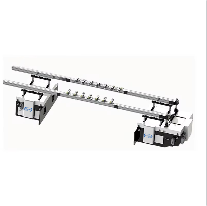
A 2 axis stamping robot arm is ideal for flat, high-speed, linear transfers between closely spaced presses. This architecture excels in automated hard tool stamping setups where parts move in a straight line from die to die. The primary advantages include extremely fast cycle times, simplified programming, and high reliability for repetitive, planar movements. Linear axes utilize robust servo motors and precision guide rails to achieve rapid acceleration.
This architecture lacks the flexibility to rotate or flip parts between stations. Applications are strictly limited to straight-line die entry and exit. If a part requires reorientation before the next forming stage, a two-axis system cannot perform the task without secondary mechanical flippers mounted between the presses. You trade flexibility for raw, linear speed.
When parts must be reoriented, flipped, or angled before entering the next die station, 6-axis articulated robots are mandatory. They offer maximum flexibility and the capability to bypass physical obstacles within the press window. This adaptability supports future product lines with complex geometries, such as automotive body panels or deep-drawn enclosures. The six degrees of freedom allow the robot to approach the die from optimal angles, ensuring precise part placement.
Articulated robots demand a larger footprint and more complex safety guarding. Point-to-point transfer speeds are slightly slower compared to dedicated linear axes. The controller must calculate complex joint kinematics for every movement, whereas a linear system simply drives a servo along a straight rail. However, the ability to repurpose a 6-axis robot for entirely different tasks makes it a highly versatile asset.
A pick and place stamping manipulator fits dedicated, ultra-high-volume production of simple components. These systems feature highly specialized, robust construction designed for relentless continuous duty. They are often integrated directly into the press frame, utilizing mechanical cams or dedicated servo drives synchronized with the press crankshaft.
The main drawback is their highly rigid application scope. Repurposing the manipulator is difficult if the manufacturing line changes or part dimensions alter significantly. They are purpose-built machines optimized for a single, repetitive task. If you run the same blanking operation for five years straight, a dedicated manipulator provides unbeatable speed and durability.
Calculating true payload requires adding the part weight, EOAT weight, and dynamic forces generated during high-speed acceleration and deceleration. Engineers must account for the inertia created when a heavy metal blank stops abruptly inside the die space. A 10kg part might exert 25kg of force during a rapid deceleration move. Undersizing the robot payload leads to premature servo failure and excessive joint wear.
EOAT options for sheet metal vary based on material properties. Vacuum grippers handle oily surfaces effectively, utilizing venturi generators to maintain strong suction even when drawing in stamping lubricants. Magnetic grippers secure ferrous materials without requiring compressed air, while mechanical clamps provide positive physical holds for heavy gauge steel. Handling thin metal sheets requires specialized EOAT and programmed acceleration curves to prevent warping, bending, or surface marring during high-speed transfers. Spring-loaded suction cups accommodate slight variations in blank thickness, while blow-off valves ensure rapid part release. Integrating sensors within the EOAT prevents "double-blanking" by detecting multiple sheets before they enter the die, saving the press from catastrophic damage.
A robust handshake between the robot controller and the press PLC is non-negotiable for punch press automation. Functional tests must map out safety protocols, ensuring the robot only enters the die space when the press is at top dead center (TDC) and mechanically locked. This requires precise I/O mapping and high-speed safety relays, often utilizing network safety protocols like PROFIsafe or CIP Safety.
The standard handshake sequence involves strict verification steps:
The press PLC signals that the ram is at TDC and the clutch is disengaged.
The robot controller verifies the "Press Safe" signal and initiates the entry motion.
The robot places the blank, releases the EOAT, and exits the press window.
The robot controller sends a "Robot Clear" signal to the press PLC.
The press PLC verifies the clear signal and initiates the downward stroke.
Modern user-friendly software interfaces allow operators to select motors, links, joints, and end effectors to build the arm's kinematics automatically. Operators can jog the robot into position, record the point, and rely on the controller to optimize the path without writing raw code.
Maximizing throughput requires simultaneous part loading and unloading at all die stations. The robot must extract the finished part exactly as the next blank is inserted. Calculating die clearance ensures the automated metal stamping production line operates without collisions. The robot arm and its tooling must have sufficient physical space to enter, release the part, and exit before the ram descends.
Engineers analyze the press stroke curve and ram velocity to program collision avoidance zones. The robot must be entirely clear of the light curtains before the press initiates its downward stroke. You must map the exact degrees of the press crank. For example, the robot might be permitted to enter the die space only after the upstroke passes 270 degrees and must be completely out before the downstroke hits 90 degrees.
Robotic press tending mandates strict adherence to safety standards like ISO 10218-1/2 and RIA R15.06. Designing the safety cell involves installing hard guarding, light curtains, laser scanners, and interlocked access gates. These measures mitigate the risk of operator proximity during maintenance or die changeovers, ensuring a secure working environment.
Safety PLCs monitor all access points, immediately halting robot motion and disengaging press clutches if a barrier is breached. Proper risk assessment matrices identify potential pinch points and establish safe distance calculations for all perimeter fencing. You cannot cut corners on safety fencing; the kinetic energy of a moving industrial robot combined with a stamping press requires absolute physical separation from human workers.
Robots require dies to be in the exact same location every time. In hard tool stamping integration, the robot arm must maintain rigid repeatability to avoid tool crashes and premature die wear. Implementing mechanical locators, such as shot pins or precision guide blocks, ensures the die is seated correctly on the bolster plate after every changeover.
Vision systems or mechanical compliance devices account for minor variations in part positioning. If a blank shifts during transfer, the compliance device allows slight lateral movement. The robot must release the part just before the pilot pins engage in progressive dies to allow for micro-alignment without faulting the robot controller. Rigidly holding a part while the die attempts to center it will trigger a force-torque fault on the robot joints.
Generic robotics experience falls short in high-vibration, high-risk stamping environments. Partnering with a specialized industrial robot arm manufacturer ensures the necessary domain expertise. Key inquiries should focus on their specific experience with multi-press linkage, hard tool stamping, and managing heavy payload dynamics.
Stamping plants are harsh environments filled with airborne oil mist, metal dust, and severe floor vibrations. The selected manufacturer must provide robots with high IP ratings and robust mechanical drivetrains capable of withstanding these brutal conditions year after year. A robot designed for cleanroom assembly will fail rapidly when exposed to the shock loads of a 1000-ton mechanical press.
Evaluating the manufacturer's mean time to repair (MTTR) and spare parts availability minimizes downtime. In a 24/7 stamping operation, waiting weeks for a replacement servo motor halts production entirely. Assessing the provision of digital twins or simulation software allows facilities to test new stamping routines offline before deploying them to the physical robot arm. Offline programming ensures that collision detection and reachability studies are completed in a virtual environment, preventing costly mistakes during physical commissioning on the plant floor.
Audit your existing press line to measure exact die clearances, bolster plate dimensions, and available floor space for safety fencing.
Calculate the dynamic payload requirements for your heaviest metal blanks, factoring in the weight of custom vacuum or magnetic end-of-arm tooling.
Map out the required I/O signals between your current press PLC and the proposed robot controller to verify handshake compatibility.
Draft a strict safety protocol compliant with ISO 10218, detailing the placement of light curtains, laser scanners, and hard guarding.
A: A 2-axis system provides rapid, linear transfers ideal for closely spaced presses and simple flat parts. It lacks rotational capabilities. A 6-axis robot offers full degrees of freedom, allowing parts to be reoriented, flipped, or angled between stations. This makes it suitable for complex geometries but slightly slower than linear systems.
A: Communication occurs through a robust PLC handshake utilizing fieldbus protocols. I/O signals and safety interlocks ensure the robot only enters the die space when the press is at top dead center and mechanically locked. This strict communication prevents catastrophic press crashes and ensures synchronized cycle times.
A: It is a specialized, rigid automation tool designed specifically for high-speed, repetitive loading and unloading of blanks. Often integrated directly into the press frame, it excels in ultra-high-volume production of simple components. However, it lacks the flexibility to adapt to frequent line changes or complex part reorientations.
A: Yes. Utilizing quick-change EOAT, programmable waypoints, and specialized vacuum grippers prevents thin metal deformation. Programmed acceleration curves ensure delicate materials are transferred rapidly without warping or surface marring during product changeovers. Sensors also detect double-blanking to protect the dies.
A: True payload is calculated by adding the weight of the heaviest metal blank, the weight of the gripper or EOAT, and a specific allowance for dynamic inertia. High-speed acceleration and deceleration generate significant force, requiring a robot with a payload rating higher than the static weight of the parts.
A: Mandatory safety features include hard fencing, light curtains, laser scanners, safety PLCs, interlocked access gates, and dedicated emergency stop circuits. These components work together to comply with ISO 10218 and RIA R15.06 standards, ensuring operators remain safe during operation and maintenance.
A: Typical operational returns manifest within 12 to 24 months. This timeline is driven by transitioning to lights-out manufacturing capabilities, achieving maximum strokes-per-minute, eliminating micro-stoppages, and significantly reducing scrap rates. Continuous, predictable output rapidly offsets the initial hardware and integration investments.


