Views: 0 Author: Site Editor Publish Time: 2026-07-22 Origin: Site
A common misconception in metal fabrication is that maximizing raw Strokes Per Minute (SPM) directly equates to increased production throughput and higher profitability. Facility managers often chase the highest possible machine speeds, assuming faster cycles automatically yield more finished parts per shift. However, this oversimplified view ignores the complex physics of metal stamping. Pushing equipment to its absolute limits creates severe engineering tension. High-speed cycling clashes with material feed limitations, accelerates tool wear, and drastically increases the risk of unplanned downtime.
Evaluating production efficiency requires a holistic framework. You must shift focus from theoretical machine speed to actual Overall Equipment Effectiveness (OEE). A press running at 800 SPM that crashes twice a day is far less profitable than a press running reliably at 400 SPM. You must balance cycle rates with tool durability, scrap removal, and material handling capabilities. This balanced approach ensures you select the right equipment for your specific facility integration needs.
Speed vs. Yield Trade-off: Maximum punch press stroke speed is only profitable if material feeding systems, scrap removal, and tool durability can match the cycle rate without degrading part quality.
Machine Architecture Matters: The choice between a pneumatic power press, mechanical flywheel, or servo-driven system dictates not just top speed, but stroke profile control and energy efficiency.
Tooling: Operating a high-speed punching machine at peak capacity exponentially increases heat generation and tool degradation, requiring advanced metallurgy and lubrication strategies.
Supplier Due Diligence: Partnering with a qualified metal stamping machine supplier requires evaluating their application engineering capabilities, not just their catalog specifications.
Understanding punch press stroke speed requires differentiating between theoretical and practical limits. "Free-running SPM" refers to the no-load speed of the ram. This is a catalog specification used for baseline comparisons. "Production SPM" is the actual speed achieved under load while feeding material, ejecting parts, and clearing scrap. The gap between these two numbers dictates true operational efficiency on the shop floor.
Stroke length, slide velocity, and available tonnage interact dynamically during every cycle. The press only delivers its rated tonnage near Bottom Dead Center (BDC). As you increase the SPM, the slide velocity increases proportionally. High slide velocities can cause severe impact shock when the punch contacts the material. Managing this impact is critical for tool survival. If the punch hits the strip too fast, the shockwave shatters the carbide tooling before the cutting action even begins.
To understand this, look at the crank angle. Tonnage drops off sharply as you move away from BDC. If your application requires high tonnage high up in the stroke—like deep drawing—running at high SPM will stall the press. The kinetic energy simply isn't there. You have to match the energy curve of the press to the tonnage curve of the die.
High SPM operations necessitate shorter stroke lengths. A long stroke running at high speeds generates excessive linear velocity, measured in feet or meters per minute. Excessive linear velocity causes catastrophic tool impact failure. Shortening the stroke keeps the impact velocity within acceptable metallurgical limits.
For example, a 1-inch stroke running at 1000 SPM has a much lower impact velocity than a 4-inch stroke running at the same speed. This is why high-speed presses typically feature very short strokes, often under 1.5 inches. The short stroke minimizes the distance the ram travels, keeping the velocity manageable while still achieving high cycle rates.
Running a press at high speeds generates significant friction and heat in the bearings, bushings, and slide guides. Thermal expansion affects the slide and connection rods. This expansion alters the shut height dynamically as the press warms up. We call this dynamic BDC drift. It directly impacts dimensional tolerances and can cause progressive dies to bottom out prematurely.
Operators must monitor shut height continuously during the first hour of operation. As the machine reaches thermal equilibrium, the BDC will shift downward. If the die is set too tight initially, this thermal expansion will cause the die blocks to smash into each other, destroying the tooling. Advanced presses use thermal compensation systems, circulating temperature-controlled oil through the frame to stabilize the machine's temperature and minimize BDC drift.
Flywheel-driven systems rely on stored kinetic energy. The stamping operation depletes this energy as the punch shears the material. The motor must recover this lost energy before the next stroke begins. Operating too fast prevents the flywheel from recovering fully. This results in insufficient energy for the actual stamping operation, leading to stalled presses and stuck dies.
You can calculate the energy required for a specific job and compare it to the energy available at a given SPM. If the job requires more energy than the flywheel can recover in the shortened cycle time, you must slow the press down, regardless of its maximum rated SPM. Ignoring this energy balance is a primary cause of motor burnout and clutch failure.
Faster is not always better in metal stamping. You must analyze the mathematical tipping point of your operations. Cycle time reductions are often negated by increased tool changeovers. Maintenance stops eat into the theoretical gains of high-speed stamping. A press running at 80% of its maximum speed often produces more good parts per shift than one running at 100%.
When the punch breaks through the material, the sudden release of pressure creates reverse tonnage. This snap-through shock sends destructive dynamic waves through the press frame. High speeds amplify this shock exponentially. It damages press frames, wears out tooling, and destroys connection rod bearings.
To mitigate reverse tonnage, you must implement specific strategies. Stepping the punches in a progressive die so they don't all break through simultaneously reduces the peak shock. Using hydraulic dampening systems built into the press bed absorbs the energy. Maintaining tight punch-to-die clearances also minimizes the snap-through effect. Ignoring reverse tonnage at high speeds guarantees premature machine failure.
High-speed operations generate immense friction at the cutting edge. This heat degrades tool steel rapidly. Specialized coatings like TiN, TiCN, or DLC are mandatory to reduce friction and prevent galling. You must also implement flood lubrication to manage thermal dynamics. Without these measures, tool life drops exponentially as SPM increases.
Select the right tool steel: PM (Powder Metallurgy) steels like M4 or CPM 10V offer superior wear resistance for high-speed blanking.
Apply appropriate coatings: Match the coating to the material being stamped to prevent micro-welding.
Optimize lubrication: Use low-viscosity, high-performance stamping fluids delivered precisely to the cutting zone.
Maintain sharp edges: Dull tools increase friction, heat, and tonnage requirements, accelerating wear.
The press stroke must synchronize perfectly with peripheral equipment. Servo roll feeders, straighteners, and uncoilers must keep pace. Faster speeds compress the available feed time window to mere milliseconds. If the feeder cannot position the material accurately within this micro-window, misfeeds and die crashes occur.
Consider a press running at 600 SPM. The entire cycle takes 100 milliseconds. The punch is in the material for perhaps 30 milliseconds. That leaves only 70 milliseconds for the feeder to advance the strip, settle, and lock into position before the pilots engage. If the feed pitch is long, the feeder must accelerate and decelerate violently, causing material slippage and camber. You must size your feeding equipment to match the dynamic requirements of the press speed.
Clearing slugs and scrap from the die area becomes a physical limitation at high speeds. Gravity is often too slow to clear scrap at 1000 SPM. You must use pneumatic blow-offs, vacuum systems, or mechanical ejectors. Failure to evacuate scrap leads to slug pulling, where the scrap comes back up with the punch and gets smashed on the next stroke, causing catastrophic die damage.
Machine architecture dictates how well a press handles speed and shock. Selecting the right frame and drive system is critical for long-term reliability. You cannot expect a standard gap-frame press to perform like a straight-side high-speed machine.
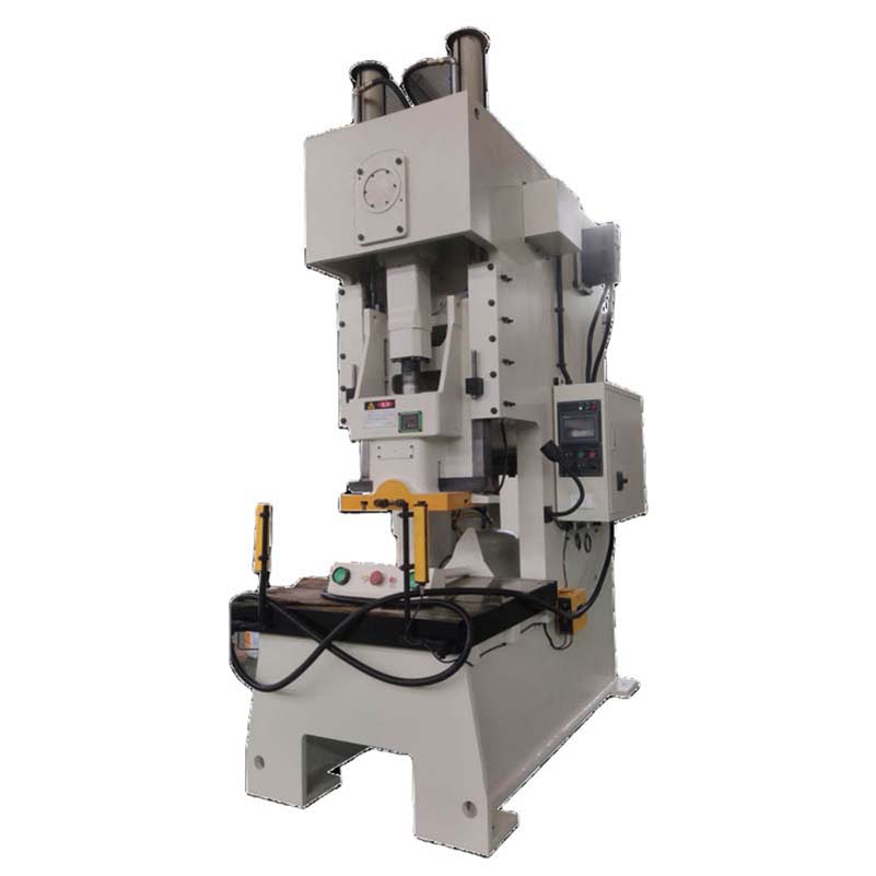
A pneumatic power press utilizes air pressure to engage the clutch and brake. This system provides rapid engagement and consistent speed regulation. It enhances operator safety through reliable stopping capabilities, allowing for integration with light curtains and other presence-sensing devices.
These machines are workhorses for general stamping. They handle a wide variety of materials and die types. However, the pneumatic clutch generates heat during engagement and disengagement. If you run the press in single-stroke mode at high frequencies, the clutch will overheat and fail. They are best suited for continuous running at moderate speeds or single-stroking at lower frequencies.
A true high-speed punching machine requires a massive, rigid structure. Cast iron frames or highly rigid H-frames are necessary to minimize deflection under load. Reciprocating slides must be dynamically balanced to handle speeds exceeding 500 to 1000 SPM without shaking the machine apart.
These presses feature specialized guiding systems, often using pre-loaded roller bearings to maintain absolute slide parallelism. The lubrication systems are highly engineered, circulating filtered, temperature-controlled oil to all critical bearing surfaces. They are designed specifically for short-stroke, high-volume production of thin materials, such as motor laminations and electronic connectors.
Servo presses replace the traditional flywheel and clutch with a high-torque servo motor directly coupled to the drive shaft. This allows for fully programmable stroke profiles. You can slow down the slide during the working portion of the stroke to protect tooling and improve material flow. You then speed up the non-working portion to maintain high overall SPM. This maximizes efficiency without sacrificing tool life.
The ability to program dwell times at BDC makes servo presses ideal for complex forming, coining, and in-die tapping operations. You get the speed of a mechanical press with the control of a hydraulic press. While the initial capital investment is higher, the flexibility and increased tool life often justify the expense for complex parts.
Matching the machine to the application requires analyzing material properties and die complexity. You cannot force a high-speed process onto inappropriate materials or poorly designed dies.
Material thickness, tensile strength, and shear-to-break ratios dictate the maximum allowable impact velocity. Harder, thicker materials require slower impact speeds to prevent punch shattering. Thin, soft materials can handle much higher impact velocities.
For example, stamping 0.5mm brass allows for very high SPM because the material shears easily and generates minimal shock. Stamping 3mm high-strength low-alloy (HSLA) steel requires a much slower speed to manage the massive impact forces and reverse tonnage. Always consult material data sheets and tooling suppliers to determine the maximum safe impact velocity for your specific application.
Progressive dies with complex forming, drawing, or tapping stations limit overall stroke speed. Simple blanking operations can run at maximum SPM. Complex forming requires dwell time for the material to flow properly without tearing or wrinkling.
If your die includes cam-actuated piercing or bending stations, the speed is limited by the mechanical return of the cams. If you run too fast, the cams will float or crash. In-die tapping units also have strict speed limits based on the thread pitch and material thickness. The slowest station in the die dictates the maximum speed of the entire press line.
Calculate true production efficiency using the OEE formula. Factor in Availability (uptime), Performance (actual vs. ideal cycle time), and Quality (defect rate). A slower press with 95% OEE outperforms a faster press with 60% OEE.
Track your downtime meticulously. If you are losing two hours a shift to clear scrap jams or replace chipped punches, your high SPM is an illusion. Slowing the press down by 15% might eliminate those jams, resulting in more net parts at the end of the week. Data-driven adjustments based on OEE metrics are the only way to optimize stroke speed.
Press Type | Optimal SPM Range | Target Material Thickness | Precision/Tolerance Level | Best Application Use Case |
|---|---|---|---|---|
Pneumatic Power Press | 50 – 150 SPM | Medium to Heavy (1.5mm - 6mm) | Standard to Medium | Heavy-duty blanking, shallow drawing, short-to-medium runs |
High-Speed Punching Machine | 300 – 1200+ SPM | Thin-Gauge (<1.2mm) | Ultra-High Precision | Connectors, lead frames, motor laminations, high-volume electronics |
Servo-Driven Press | Variable (Programmable) | Versatile (Thin to Heavy) | High to Extremely High | Complex progressive forming, deep drawing, exotic alloy stamping |
Deploying high-speed equipment introduces significant facility and operational risks. You must prepare your infrastructure and your workforce before installation. Dropping a 1000 SPM press onto a standard shop floor is a recipe for disaster.
High-speed stamping generates massive kinetic energy. Standard concrete floors will crack under this stress. You must install structural facility upgrades. Isolation pads, reinforced concrete foundations, and vibration dampening mounts are mandatory to absorb the shock and prevent it from transmitting through the building.
Consult with a structural engineer to design an isolated foundation block. This usually involves cutting the existing floor, digging a pit, pouring a massive concrete block isolated by specialized dampening materials, and mounting the press to this block. This prevents the high-frequency vibrations from destroying nearby sensitive equipment like CMMs or grinding machines.
Operating a punch press machine at high speeds requires strict adherence to safety standards. Review OSHA, ANSI (B11.1), and ISO requirements. Ensure guarding, light curtains, and stopping times are calibrated for high-velocity operations.
The stopping time of a press running at 800 SPM is vastly different than one running at 60 SPM. You must calculate the safe distance for light curtains based on the actual stopping time of the press at its maximum speed. Regular brake inspections and stopping time measurements are critical to ensure operator safety and regulatory compliance.
High-speed equipment requires advanced technical skills. Operators and maintenance personnel must manage tight tolerances, complex feed timing, and sophisticated lubrication systems. Invest heavily in training to prevent catastrophic machine damage caused by setup errors.
A minor misadjustment in feed pitch or pilot release timing that might cause a slight mark on a part at 60 SPM will cause a massive die crash at 600 SPM. Operators must understand the dynamic relationship between the press, the feeder, and the die. Implement standardized setup procedures and require sign-offs for all critical adjustments.
Procuring high-speed equipment requires a strategic partnership. You must vet suppliers based on their engineering competence, not just their sales brochures. A reliable supplier acts as an extension of your engineering team.
Evaluate a metal stamping machine supplier by their ability to perform rigorous pre-sale engineering. They should provide tonnage calculations, energy curve analysis, and detailed time studies based on your specific part prints. If they cannot prove the process on paper, do not buy the machine.
Ask them to analyze your most difficult die. Have them calculate the required energy per stroke and compare it to the press's capacity. They should be able to recommend the optimal stroke length, motor size, and flywheel configuration for your specific product mix.
Establish strict baseline requirements for factory acceptance testing (FAT). Demand proof of sustained stroke speed using your actual production dies and materials. A dry run without material proves nothing about production capability.
The FAT should include running the press at the target SPM for a sustained period—at least several hours—while monitoring bearing temperatures, vibration levels, and part quality. Verify that the material feeding system can maintain accuracy at the target speed. Do not sign off on the machine until it proves it can handle your real-world production demands.
High-speed presses require reliable maintenance support. Evaluate the supplier's domestic parts inventory. Check their field service response times. Ensure they offer comprehensive preventative maintenance programs to protect your investment.
Ask for references from other customers running similar high-speed applications. Inquire about the availability of critical spare parts like clutch plates, brake linings, and specialized bearings. A machine down for weeks waiting for parts from overseas destroys any ROI calculations.
Conduct a thorough OEE audit of your current stamping operations to identify true bottlenecks before purchasing new equipment.
Request detailed time-studies and energy curve analyses from prospective suppliers to verify machine capabilities.
Evaluate your facility's foundation and vibration isolation capabilities and complete necessary civil engineering upgrades prior to installation.
Upgrade your material feeding, straightening, and scrap evacuation systems to match the dynamic requirements of your target press speeds.
Implement a rigorous preventative maintenance schedule focused on lubrication, brake inspections, and thermal monitoring.
A: Stroke speed (SPM) is the number of complete cycles the press makes per minute. Slide velocity is the actual linear speed of the ram as it travels through the stroke, usually measured in feet or meters per minute. High SPM requires shorter strokes to keep slide velocity manageable and prevent tool impact failure.
A: Increasing speed generates exponentially more heat and friction at the cutting edge. It also increases the impact shock when the punch hits the material. Without proper coatings, lubrication, and vibration dampening, tool life will decrease rapidly at higher speeds due to thermal degradation and micro-chipping.
A: Dynamic BDC drift is the change in the press's shut height caused by thermal expansion of internal components running at high speeds. As the connection rods heat up and expand, the punch penetrates deeper, which can alter part tolerances and cause progressive dies to bottom out prematurely.
A: Reverse tonnage is the snap-through shock created when the punch breaks through the metal. High SPM amplifies this shockwave, which travels back up through the press frame. Over time, this can crack frames, destroy bearings, and shatter tooling if not properly dampened.
A: As press speed increases, the time available to feed the material forward shrinks to milliseconds. If the servo feeder cannot accelerate, move, and stop the material precisely within this tiny window, misfeeds and die crashes will occur. The feeder mechanics must match the press dynamics.
A: No. Standard presses lack the structural rigidity, dynamic balancing, and specialized lubrication systems required for high speeds. Pushing a standard press beyond its design limits will cause severe frame deflection, rapid clutch failure, and catastrophic bearing damage.