


Views: 0 Author: Site Editor Publish Time: 2026-10-20 Origin: Site


Inconsistent bending angles destroy production schedules and inflate operational costs. Scrap rates climb rapidly. Operators waste valuable hours manually reworking parts. Assembly lines stall while waiting for accurate components. High-tolerance fabrication demands precision, and chasing the perfect angle drains profitability.
When a press brake produces varying angles on the exact same program, the root cause rarely points to a single operator error. The problem usually spans material inconsistency, improper setup, tooling wear, or hydraulic drift. Blaming the operator is easy, but diagnosing the mechanical and material realities solves the actual problem.
We will establish a systematic framework to diagnose these frustrating inconsistencies. You will learn how to evaluate material variables, inspect tooling integrity, and check hydraulic synchronization. This guide helps you decide whether the problem requires routine calibration, tooling replacement, or an upgrade to a more capable machine.
Material variability (thickness, tensile strength, grain direction) is the most frequent non-mechanical cause of angle inconsistency, directly impacting springback.
Operator setup errors, including incorrect tonnage calculations and off-center bending, can force a perfectly aligned machine to produce tapered bends.
Tooling wear, improper upper/lower die alignment, and crowning setup failures lead to localized deflection, often resulting in "canoeing" along the bend line.
Hydraulic synchronization issues in Y1/Y2 axes or degrading proportional valves can cause the ram to descend unevenly, destroying repeatability over time.
Persistent inconsistencies on aging equipment often necessitate a cost-benefit analysis between investing in press brake technical support/retrofits versus procuring a modern metal forming press machine.
Even a perfectly calibrated machine produces inconsistent angles if the input material fluctuates. You must isolate material variables before adjusting any machine parameters. Success requires understanding how the metal behaves under pressure and recognizing that mill tolerances are often wider than your fabrication tolerances.
Standard mill tolerances allow significant thickness variations within the exact same batch of sheet metal. For example, a sheet of 10-gauge mild steel might measure 0.134 inches on one end and 0.140 inches on the other. A slight increase in thickness forces the punch deeper into the V-die during air bending. This deeper penetration creates an over-bent angle. Conversely, thinner material results in an under-bent angle. You cannot achieve consistent bends if the material thickness constantly changes.
Tensile strength variations directly correlate to unpredictable springback. Harder spots in the sheet resist deformation during the stroke. They spring back further when the ram retracts. Two sheets cut from the same master coil can exhibit different yield strengths. High-strength low-alloy (HSLA) steels exhibit even more erratic springback than standard A36 mild steel. This forces operators to constantly tweak the bend allowance and angle corrections.
Material Variable |
Physical Effect During Bending |
Impact on Final Angle |
|---|---|---|
Increased Thickness |
Punch penetrates deeper relative to the neutral axis. |
Over-bent (acute) angle. |
Decreased Thickness |
Punch fails to reach the required depth for the target angle. |
Under-bent (obtuse) angle. |
Higher Yield Strength |
Material resists plastic deformation more aggressively. |
Increased springback; under-bent angle. |
Lower Yield Strength |
Material yields easily with less resistance. |
Decreased springback; over-bent angle. |
Sheet metal possesses a distinct grain direction created during the rolling process at the mill. Bending parallel to the grain requires less tonnage but increases the risk of outer radius cracking. Bending perpendicular to the grain requires more force and alters the springback profile completely. Mixing grain directions across a single production run guarantees inconsistent angles. Operators must identify the grain direction before loading the blank.
Thermal history also plays a critical role in material behavior. Laser cutting and plasma cutting create heat-affected zones (HAZ) along the part edges. Nitrogen or oxygen assist gases used during laser cutting harden the edge of the material. Hardened edges resist bending differently than the softer center of the sheet. This thermal distortion causes noticeable angle drift at the extreme edges of the part, often confusing operators who assume the machine is out of parallel.
Implement strict material inspection protocols before the metal reaches the forming department. Measure sheet thickness using digital calipers before starting any new batch. Sort blanks by grain direction to maintain consistent forming resistance. For critical tolerance parts, utilize controllers equipped with real-time angle measurement. These advanced systems actively monitor the bend and provide springback compensation on the fly. This eliminates the need for manual test bends and reduces scrap, ensuring high CNC press brake bending accuracy regardless of minor material fluctuations.
Before blaming the hardware, rule out programmable and procedural mistakes. Setup errors lead to inaccurate bends, material waste, and severe tooling damage. A systematic setup process prevents these unforced errors and protects the equipment from premature wear.
Applying excessive tonnage for a specific material thickness causes unnecessary machine deflection. The ram and bed bow under the extreme force. This deflection permanently damages the frame over time. Operators often increase tonnage hoping to force a stubborn material into shape, especially when using a V-die that is too small for the material thickness. This approach ruins tooling and degrades overall accuracy.
Bottoming a part when the program is set for air bending creates massive tonnage spikes. The machine attempts to push the punch into the die past the material's yield point. This crushes the material and overloads the hydraulic system. Always verify the required tonnage against the machine's maximum capacity chart before initiating the stroke. A standard rule of thumb is to use a V-opening that is 8 times the material thickness for mild steel.
A perfectly aligned ram at Top Dead Center (TDC) can still produce tapered bends. This happens when operators consistently bend small parts on the far left or right side of the bed. Off-center loading unevenly stresses the hydraulic cylinders and the side frames.
The cylinder closest to the work does all the heavy lifting. The opposite cylinder pushes against empty space. This imbalance creates temporary yaw during the downward stroke. Over time, this practice leads to permanent frame deformation and damages the gib clearances. Always center the workload on the bed whenever possible. If you must bend off-center due to staging requirements, distribute the load by setting up dummy blocks of the same thickness on the opposite side of the bed.
To eliminate operator-induced angle variations, enforce a strict setup sequence for every new job.
Verify the actual material thickness of the current batch using digital calipers.
Calculate the required tonnage based on the material type, thickness, and selected V-die opening.
Inspect the punch and die for any visible wear, galling, or debris before installation.
Center the tooling setup on the machine bed to ensure equal load distribution across both hydraulic cylinders.
Perform a dry run without material to verify backgauge positioning and check for any tooling interference.
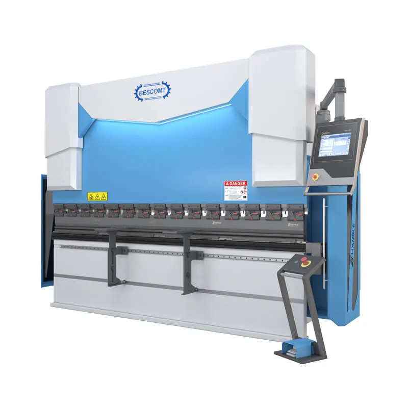
Tooling serves as the direct point of contact between the machine and the material. Minor wear or misalignment translates to major angle discrepancies. Maintaining pristine tooling is non-negotiable for precision fabrication. You cannot produce accurate parts with degraded punches and dies.
Misaligned tools are a primary culprit behind angle issues. Ensure upper punches and lower V-dies are perfectly seated and centered. A punch slightly off-center pushes material unevenly into the die cavity. This creates a bend featuring different leg lengths and an inconsistent angle from one end to the other.
Clean the tool holders and tangs thoroughly before clamping. Even a small metal shaving trapped between the punch and the holder throws the alignment off by several thousandths of an inch. Seat the tools properly by applying light tonnage (pinching the tools together) before fully tightening the clamps. Use a dial indicator to verify that the lower die is perfectly parallel to the backgauge fingers.
Tooling wears down over thousands of cycles. Uneven V-die wear typically manifests as widened shoulders. A wider shoulder changes the leverage point during air bending. This results in a consistently under-bent angle. Asymmetric punch tips push the bend line off-center, ruining the part geometry and causing the material to drag unevenly into the die.
Never mix tooling segments from different manufacturers across a single bend line. Do not mix brand-new segments alongside heavily worn segments. The height differences, even measured in microns, will destroy the bend accuracy. Conduct regular tooling audits and replace worn segments in complete sets. European precision-ground tooling offers better repeatability than traditional planed tooling, but it still requires strict maintenance.
Tooling Defect |
Visual Symptom |
Impact on Production |
|---|---|---|
Widened V-Die Shoulders |
Shiny, flattened edges on the top corners of the die. |
Causes under-bending; alters the inside radius of the part. |
Flattened Punch Tip |
Loss of the sharp radius at the apex of the punch. |
Increases required tonnage; causes erratic springback. |
Galling |
Material welded to the tooling surfaces (common with aluminum). |
Scratches the workpiece; creates uneven friction during the bend. |
The ram and bed naturally bow under heavy tonnage. This deflection causes the center of the bend to be under-bent compared to the outer ends. Fabricators often call this phenomenon "canoeing". Crowning systems compensate for this deflection by pushing the center of the bed upward to meet the bowing ram.
Manual wedge crowning requires careful operator adjustment based on test bends. CNC hydraulic crowning automatically adjusts upward pressure based on program parameters and material resistance. Do not over-adjust the crowning system to compensate for worn tooling. This masks the root problem and accelerates wear on the crowning mechanism itself. If you have to max out the crowning adjustment to get a straight bend, your tooling is likely compromised or your bed is permanently warped.
Differentiating between a programmable error and a physical hardware failure is crucial. This distinction matters most when a machine suddenly drifts after years of perfect operation. Mechanical degradation requires immediate technical intervention to prevent catastrophic failure.
In an aging hydraulic press brake, proportional directional valves degrade over time. Cylinder seals begin to leak internally, allowing fluid to bypass the piston. These issues cause the Y1 and Y2 cylinders to fall out of parallel alignment. The ram descends unevenly, applying different pressure to each side of the part.
Tapered bends result directly from this uneven tonnage application. Diagnosing pressure imbalances requires checking hydraulic pressure gauges during the active stroke. If the pressure drops on one side, the synchronization is failing. This requires immediate valve calibration or seal replacement. Ignoring a leaking cylinder forces the proportional valves to work harder to maintain level, eventually burning out the valve coils.
Linear encoders, commonly known as glass scales, maintain micron-level ram positioning. They communicate the exact ram position back to the controller in real-time. Dirt, dust from grinding operations, or oil contamination on these scales destroys the feedback loop. The controller receives false positioning data and stops the ram at the wrong depth, resulting in wild angle variations.
Thermal expansion of hydraulic oil throughout a long shift also causes positioning issues. As oil heats up, its viscosity drops. Thinner oil flows faster through the valves. This causes TDC and bottom-dead-center (BDC) drift if the machine lacks thermal compensation software or an active oil chiller. Run the machine through several dry cycles at the start of a shift to warm the oil to operating temperature before bending the first production part.
The backgauge determines the exact flange length. Worn ball screws, damaged linear guides, or loose drive belts cause the fingers to position inconsistently on the X, R, and Z axes. A varying flange length indirectly alters the bending leverage. If the material sits differently on the V-die shoulders from one cycle to the next, the final angle changes.
Regularly calibrate the backgauge using precision gauge blocks. Check for excessive backlash in the ball screws by physically pushing and pulling on the backgauge bar. If the backgauge fingers exhibit physical play, the mechanical drive components require immediate replacement. A highly accurate ram is useless if the backgauge cannot position the blank consistently.
The chosen bending technique dictates the required machine accuracy. Aligning your method with your production expectations prevents unnecessary frustration. Different methods require different tooling geometries and vastly different tonnage capacities.
Understanding the physics behind each method helps diagnose angle problems quickly. Air bending is the most common, but it is also the most sensitive to the variables discussed earlier.
Bending Method |
Mechanism |
Accuracy Dependency |
Tonnage Requirement |
|---|---|---|---|
Air Bending |
Punch pushes material into the die without touching the bottom. |
Highly sensitive to material variations and ram positioning accuracy. |
Relatively low. Ideal for most standard fabrication. |
Bottoming |
Punch forces material against the V-die walls. |
Relies on tooling geometry rather than ram depth precision. |
High. Requires 3 to 5 times more force than air bending. |
Coining |
Extreme tonnage forces punch tip into the material's neutral axis. |
Eliminates springback entirely through sheer force. |
Extremely high. Rarely used due to severe tooling and machine wear. |
Evaluate the trade-off between flexibility and brute force. Air bending offers maximum flexibility. You can form multiple angles using the exact same tooling setup simply by changing the ram depth. However, air bending requires highly accurate ram control and consistent material. If your material thickness varies, your air-bent angles will vary.
Bottoming provides brute-force consistency but limits your flexibility. You need specific tooling for every single angle you intend to bend. Bottoming also risks severe machine overload if the operator miscalculates the required tonnage or uses the wrong die. Air bending paired with active angle correction stands as the modern industry standard. It combines supreme flexibility with high precision, mitigating the traditional downsides of air bending.
Chronic inconsistency requires a decisive action plan. You must evaluate whether to repair, upgrade, or replace the equipment. Use a structured framework to make this operational decision rather than throwing money at random fixes.
Call OEM technicians when basic troubleshooting fails to resolve the drift. Seek press brake technical support for the recalibration of linear scales. Technicians must handle complex hydraulic valve tuning and pressure imbalance adjustments. They possess the specialized diagnostic software required to read valve response times.
Software updates and controller diagnostics also require expert intervention. Do not attempt to adjust proportional valves without proper training and pressure testing equipment. Incorrect adjustments will worsen the synchronization issues and potentially cause the ram to drop unexpectedly.
Assess the return on upgrading specific machine components. Adding a motorized CNC crowning system eliminates the need for manual shimming with paper or metal strips. This drastically reduces setup time and eliminates the "canoeing" effect. Upgrading to precision-ground, hardened tooling instantly improves repeatability across the entire bed length.
Retrofits extend the life of a mechanically sound frame. If the side frames remain rigid, the gibs are tight, and the hydraulic cylinders hold pressure without leaking, upgrading the controller or backgauge provides excellent value. However, retrofits cannot fix a permanently warped bed or cracked side frames.
Identify the threshold where maintenance costs, scrap rates, and lost production hours exceed new equipment financing. Persistent inconsistencies on aging equipment often necessitate a new metal forming press machine. When downtime ruins your delivery schedules and forces you to outsource forming work, replacement becomes mandatory.
Look for modern features when evaluating a new CNC bending machine for steel sheet. Dynamic crowning, laser angle measurement, and hybrid-servo drives permanently eliminate legacy inconsistency issues. Upgrading to a modern sheet metal bending machine dramatically increases throughput, reduces reliance on highly skilled operators, and guarantees perfect angles on the first bend.
Conduct a comprehensive tooling audit using a dial indicator to identify and discard worn or mismatched segments.
Implement strict material inspection protocols to measure sheet thickness and identify grain direction before bending begins.
Schedule a preventative maintenance check to clean linear scales, inspect hydraulic seals, and verify Y1/Y2 synchronization.
Consult an applications engineer to evaluate if your current equipment meets your tolerance requirements or if a machine replacement is necessary.
A: Tapered bends often result from localized tooling wear or uneven crowning. Off-center bending loads also stress the frame unevenly. Bending exclusively on one side of the bed causes temporary yaw in the hydraulic cylinders, leading to a taper.
A: Thickness variance directly changes the inside radius during air bending. Thicker material forces the punch deeper into the V-die, creating an over-bent angle. Thinner material results in an under-bent angle. This variance also alters the springback profile.
A: Mechanical brakes rely on a rigid, fixed stroke driven by a flywheel, making them fast but less adaptable. Hydraulic brakes use programmable, encoder-monitored strokes. This allows precise depth control and active adjustments, offering superior consistency for complex parts.
A: Yes. Worn V-dies typically widen at the shoulders. This widens the leverage point and causes under-bending. Flattened or asymmetric punch tips push the bend line off-center. Mixing worn and new tooling guarantees angle variations.
A: Contact support after verifying material consistency, tooling integrity, and basic program parameters. If the machine still drifts, you likely need expert help for linear scale recalibration, hydraulic valve tuning, or fixing pressure imbalances.
A: Fixing a pressure imbalance requires proportional valve calibration and seal inspection. You must monitor pressure gauges during the active stroke. This complex task requires qualified hydraulic technicians to prevent further synchronization damage.
A: Air bending is more sensitive to material thickness and tensile variations. However, it is highly accurate when paired with modern CNC controls, precision tooling, and active angle measurement systems. It offers greater flexibility than bottom bending.


