English

Views: 0 Author: Site Editor Publish Time: 2026-10-19 Origin: Site
Escalating global demand for standardized electrical enclosures directly follows rapid commercial infrastructure and residential construction growth. Plastic enclosures serve basic residential needs, but NEMA OS 1 galvanized steel boxes remain strictly mandated for surface-mounted, concrete-embedded, and heavy-duty commercial applications. This strict regulatory environment justifies the capital expenditure required for advanced metal forming equipment. Legacy manufacturing operations face severe operational bottlenecks. High scrap rates, frequent tooling wear, inconsistent knockout tolerances, and the labor-intensive nature of semi-automated stamping destroy profit margins. Manufacturers must transition to fully automated solutions to survive. You are tasked with sourcing and implementing a modern junction box making machine to optimize unit economics and ensure regulatory compliance. We will dissect the machinery, tooling, and operational strategies required to build a highly profitable, continuous-feed manufacturing ecosystem.
Automation is Non-Negotiable: Transitioning to a fully automated electrical junction box production line reduces per-unit cost and minimizes operator intervention.
Tooling Dictates Quality: The integration of a high-precision progressive stamping die is the critical factor in maintaining consistent knockout dimensions and structural integrity.
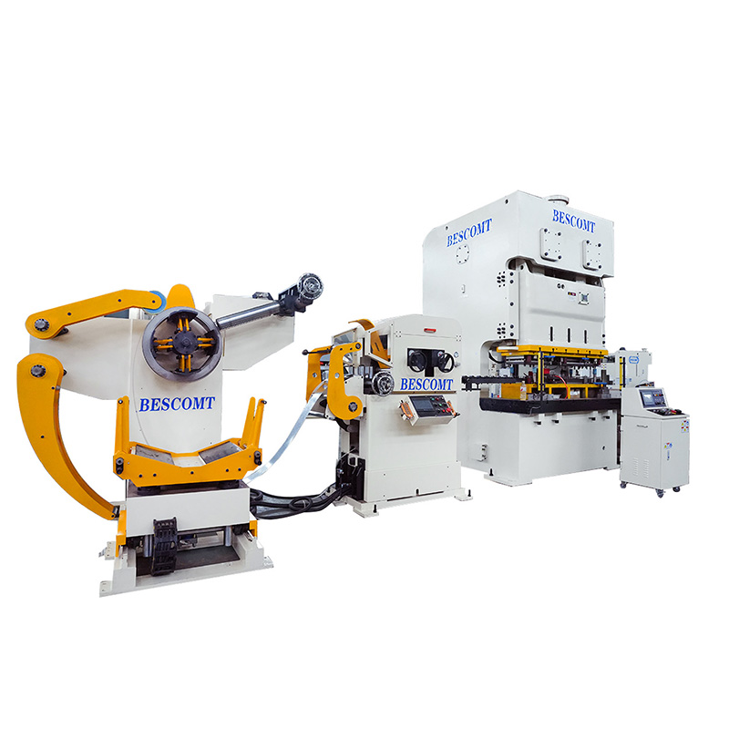
Material Handling Efficiency: Utilizing a 3-in-1 decoiler straightener feeder minimizes footprint while ensuring the precise material tension required for high-speed stamping.
Regional & Application Standards Drive Specifications: Machine selection must align strictly with target market regulations, requiring distinct tooling for American vs. European standards, as well as specific configurations for new-work versus remodeling installations.
A continuous-feed manufacturing ecosystem transforms raw galvanized steel coils into finished, compliance-ready electrical boxes without manual intervention. This system relies on synchronized mechanical actions. Raw material enters one end, undergoes severe mechanical deformation, and exits as a fully formed, threaded, and assembled enclosure. Building a reliable electrical junction box production line requires understanding how each module interacts with the next.
To evaluate success, engineers establish strict baseline metrics. Strokes Per Minute (SPM) dictates raw output capacity. Overall Equipment Effectiveness (OEE) measures availability, performance, and quality. Scrap percentage tracks material waste, which directly impacts profitability. Finally, die changeover times determine how quickly a facility can pivot between different product SKUs. Optimizing these four metrics guarantees a rapid return on equipment investment.
The primary machinery stations map out the production flow. First, material handling equipment manages the heavy steel coils. Next, the primary stamping press provides the necessary force. Inside the press, specialized tooling cuts and shapes the metal. Finally, secondary automated units handle tapping and component assembly. Each stage must communicate flawlessly via a centralized PLC control system to prevent catastrophic crashes.
Operational Metric | Legacy Semi-Automated Stamping | Modern Automated Production Line |
|---|---|---|
Operator Intervention | High (Manual blank loading, manual transfer) | Minimal (Coil loading and system monitoring only) |
Scrap Rate | 8% - 12% due to misfeeds and manual errors | Under 3% with optimized strip layouts |
Knockout Consistency | Variable, dependent on operator alignment | Exact, controlled by progressive die pilots |
Die Changeover Time | 4 - 6 hours with manual clamping | Under 30 minutes with Quick Die Change (QDC) |
Transitioning from legacy systems to modern automation requires a complete overhaul of floor space planning. You must account for the looping pit required by the material feeder, the footprint of the primary press, and the run-out conveyors for finished parts. Proper alignment of these components prevents material binding and ensures the steel strip feeds perfectly parallel to the die matrix.
Manufacturing begins with uncoiling heavy gauge galvanized sheet metal. Coils often weigh several tons and contain immense internal kinetic energy. The uncoiling process must be controlled precisely to prevent material runaway. You need robust machinery to handle this initial stage safely and efficiently. Operators follow strict protocols when loading new coils to prevent material damage and ensure operator safety.
The overhead crane positions the raw galvanized coil onto the expansion mandrel.
Hydraulic wedges expand the mandrel to grip the inner diameter of the coil securely.
The operator threads the leading edge of the steel strip through the peeler table and into the pinch rollers.
The system engages the straightener bank to remove the initial coil set.
This is the exact role of a 3-in-1 decoiler straightener feeder. This integrated unit saves floor space and synchronizes material flow. The straightener module forces the metal through a series of staggered rollers. This action removes the coil set and internal stresses from the steel. Flattening the metal ensures precise feeding into the press. Flat material prevents die jams, eliminates material buckling, and extends tooling life significantly.
Feed pitch accuracy is paramount. Servo-driven feeding mechanisms maintain micro-millimeter accuracy for progressive stamping. If the feed pitch is off by a fraction of a millimeter, the progressive tooling will strike the wrong area. This causes instant part rejection and potential die damage. Servo motors provide the exact tension and speed control required for high-speed, error-free feeding. The feeder communicates directly with the press encoder, advancing the material only during the safe window of the press stroke.
Once the flat steel enters the press, the forming process begins. The sequential stations within a progressive stamping die execute multiple operations per stroke. The strip moves through piercing, drawing, bending, and blanking stations. Each station performs a specific cut or bend. The final station severs the completed box from the scrap skeleton. Pilot pins engage pre-punched holes in the strip to guarantee perfect alignment before the punches make contact.
Knockout creation demands exceptional tooling precision. You must create concentric and eccentric knockouts that remain secure during transport and concrete pouring. However, they must also be easily removed by electricians on-site using standard hand tools. Achieving this balance requires precise clearance between the punch and die. If the cut is too deep, the knockout falls out prematurely. If it is too shallow, the electrician cannot remove it. Tooling engineers use specialized coining stations to compress the metal slightly around the knockout, creating a secure friction fit.
Deep drawing forms the actual walls of the box. The physics of drawing galvanized steel are complex. You must stretch the metal without compromising the protective zinc coating. Excessive friction causes micro-fractures in the box walls or strips the galvanization. Engineers use specialized drawing compounds, polished carbide radii, and controlled blank holder pressure to maintain wall integrity and corrosion resistance. The drawing process often occurs over multiple stations to prevent material tearing, gradually forming the box to its final depth.
Modern production lines integrate secondary operations directly into the workflow. In-die tapping or secondary automated threading stations create the necessary threads for grounding screws and mounting brackets. Performing these operations inline eliminates the need for secondary manual handling. Automated tapping heads synchronize with the press stroke, ensuring every box features perfect threads. These tapping units utilize roll-form taps rather than cutting taps to prevent metal chips from contaminating the die area.
Component assembly varies based on specific installation requirements. Automated riveting or spot-welding processes attach internal cable clamps and grounding pigtails. Specialized mounting hardware requires precise alignment. For example, metal retention straps for old-work remodeling boxes differ vastly from direct-nail brackets used in new construction. Automated assembly stations use vibratory bowl feeders and robotic pick-and-place units to position and secure these components flawlessly. Sensors verify the presence and correct orientation of every bracket before the final assembly is discharged into the packaging bin.
Determining the necessary press capacity requires careful calculation. You must base tonnage requirements on material thickness, box depth, and the number of progressive die stations. A simple handy box might require a 110-ton press. A deep-drawn, multi-gang masonry box could demand a 250-ton press. Under-sizing the press leads to excessive frame deflection and premature motor failure. Engineers calculate the total cutting force, drawing force, and stripping force to determine the absolute minimum tonnage required.
Box Type | Typical Material Gauge | Required Tonnage Range | Recommended Press Frame |
|---|---|---|---|
Standard Handy Box (2x4) | 16 Gauge (1.5mm) | 110 - 160 Tons | C-Frame or H-Frame |
4-Inch Square Box (1.5" Deep) | 16 Gauge (1.5mm) | 160 - 200 Tons | H-Frame (Straight Side) |
Multi-Gang Masonry Box (2.5" Deep) | 14 Gauge (1.9mm) | 250 - 300 Tons | H-Frame (Straight Side) |
Octagonal Ceiling Box | 16 Gauge (1.5mm) | 160 - 200 Tons | H-Frame (Straight Side) |
Frame construction directly impacts die life and high-speed stability. Buyers must evaluate the trade-offs between C-frame and straight-side (H-frame) presses. C-frame presses offer excellent accessibility for die changes but suffer from angular deflection under heavy loads. Straight-side H-frame presses provide superior structural rigidity. This rigidity minimizes deflection, drastically extends tooling life, and ensures consistent knockout tolerances during high-speed runs. For progressive stamping of galvanized steel, the H-frame press is the industry standard.
Target markets dictate machine and tooling specifications. An American standard junction box making machine requires specific tooling for NEMA-compliant boxes. These include 4-inch square boxes, handy boxes, and octagonal boxes. The tooling must accommodate specific cable clamp integrations and standardized knockout patterns dictated by the National Electrical Code (NEC). The dies must also form the specific grounding bumps required for American installations.
Conversely, a European standard junction box making machine focuses on IEC/BS-compliant enclosures. These typically involve 3x3 inch configurations, varied depth requirements, and specific conduit entry points. European standards often require different grounding provisions and mounting lug configurations compared to their American counterparts. The tooling must account for metric conduit sizes and specific fire-rating requirements mandated by European building codes.
Changeover efficiency is a critical evaluation metric. Facilities rarely produce a single SKU continuously. Assess the machine's capability to swap dies efficiently when switching between regional standards or box sizes. Quick Die Change (QDC) systems, hydraulic die lifters, and automated clamping mechanisms reduce changeover times from hours to minutes. This flexibility maximizes machine uptime and overall profitability. Operators use standardized die carts to roll the heavy tooling directly into the press bed, eliminating the need for dangerous forklift maneuvers.
Electrical boxes serve different phases of construction. Evaluate the machine's ability to seamlessly switch between producing old-work boxes and new-work boxes. Old-work (remodeling) boxes require specialized plaster ears and metal retention straps to grip existing drywall. New-work boxes feature angled nails or heavy-duty brackets for direct attachment to exposed wall studs. The production line must accommodate these different hardware feeding systems without requiring a complete teardown of the assembly module.
Concrete and surface-mounted applications present unique challenges. Concrete-cast boxes require extreme tooling precision. The knockouts must resist the hydrostatic pressure of wet concrete slurry ingress. Any leakage ruins the box and the conduit run. Surface-mounted sheet metal boxes (NEMA 250) demand high aesthetic and structural quality. They must lack sharp burrs and feature perfectly formed corners to ensure safe interaction in exposed commercial environments. Tooling engineers use specialized corner-forming stations to fold the metal tightly without leaving sharp, exposed edges.
Forward-thinking buyers evaluate machines based on modular upgradeability. Can the system integrate future modules? You may eventually need automated packaging systems, inline quality inspection sensors, or robotic palletizers. A rigid, closed-architecture machine limits future growth. Look for open PLC architectures and physical space within the line layout for expansion. Ensure the main control panel has spare I/O blocks to accommodate future sensor arrays or auxiliary equipment.
Sometimes standard machines fall short of proprietary requirements. Commissioning a custom metal stamping production line solves this issue. Custom lines are tailored to proprietary box designs, unique mounting techniques, or specialized architectural requirements. When specifying a custom line, clearly define your required cycle times, material specifications, and floor space constraints to the machinery manufacturer. You must also provide detailed 3D CAD models of the final product to ensure the custom tooling can achieve the required geometries.
High-speed stamping of galvanized steel causes rapid abrasive wear on punches and dies. The zinc coating flakes off and acts as an abrasive powder. This wear leads to burrs on knockouts, out-of-tolerance boxes, and eventual die failure. Ignoring tooling wear guarantees high scrap rates and rejected shipments. The constant friction generates immense heat, which further degrades the cutting edges of the tool steel.
Implement predictive maintenance schedules to mitigate this risk. Utilize carbide tooling for high-wear stations like piercing and knockout forming. Integrate acoustic or tonnage monitors into the press control system. These sensors detect minute changes in stamping force, alerting operators to die wear before catastrophic failure occurs. Regular sharpening and lubrication protocols are mandatory. Operators must clean the die matrix daily to remove accumulated zinc dust and prevent galling.
Inefficient strip layouts in the progressive die lead to excessive skeleton scrap. When you stamp millions of boxes, a 2% increase in material waste destroys profit margins. Steel costs dominate the unit economics of junction box manufacturing. You cannot afford poor material utilization. Every millimeter of wasted steel translates directly to lost revenue over the lifespan of the production run.
Require die designers to provide detailed strip layout simulations during the procurement phase. These simulations verify maximum material utilization and optimal grain orientation. By nesting the box blanks tightly within the steel strip, engineers can minimize the webbing width. Proper scrap management also requires automated scrap choppers or conveyors to remove the skeleton efficiently from the press area. The scrap chopper cuts the skeleton into small, manageable pieces that fall directly into a recycling bin, preventing dangerous material buildup around the press.
Misfeeds or slug pulling cause catastrophic die crashes. If a pierced slug pulls back up out of the die matrix, the next stroke will smash it into the strip. This shatters tooling and bends the press ram. Misfeeds occur when the material slips or binds, causing the punches to hit half-holes. A single die crash can halt production for weeks while replacement components are machined.
Ensure the machine is equipped with comprehensive sensor arrays. Install misfeed sensors at the die entrance. Use slug detection sensors in the die matrix. Implement automated emergency stop protocols tied directly to these sensors. A fast-acting clutch and brake system on the press will halt the ram mid-stroke, saving the tooling from destruction. Operators must also verify that the straightener is functioning correctly, as bowed material is the primary cause of binding within the die guides.
Request comprehensive cycle time simulations from shortlisted machinery OEMs to verify actual production output against your required quotas.
Demand detailed strip layout proposals during the quoting phase to ensure maximum material utilization and minimal skeleton scrap.
Audit the proposed PLC architecture to confirm it supports open protocols for future integration of automated packaging and inline inspection modules.
Specify tungsten carbide inserts for all high-wear piercing and knockout stations to extend die life and reduce maintenance downtime.
Require verifiable OEE data and on-site case studies from similar installations before signing the final procurement contract.
A: Modern automated lines typically run between 40 and 80 Strokes Per Minute (SPM). The exact speed depends on the box depth, material thickness, and the complexity of the progressive die. Shallow handy boxes run faster, while deep-drawn masonry boxes require slower speeds to prevent metal tearing.
A: It removes coil set and internal stress from the raw steel. By flattening the material perfectly before it enters the press, it prevents binding in the die, ensures accurate feed pitches, and eliminates dimensional variations in the finished electrical boxes.
A: Yes, the primary press and feeding equipment can handle both. However, you must purchase and swap distinct progressive stamping dies for each standard. The machine needs sufficient tonnage and a large enough bed size to accommodate the different tooling dimensions.
A: The core box is stamped using the same primary die. The adaptation occurs in the secondary assembly stations. The line uses automated riveting or welding modules to attach specific hardware, such as plaster ears for old-work or direct-nail brackets for new-work.
A: Stamped boxes are formed from cold-rolled galvanized steel coils using high-tonnage presses and progressive dies. Cast metal boxes are created by pouring molten aluminum or iron into molds. Stamping is faster and cheaper for high-volume indoor use, while casting provides thicker walls for harsh outdoor environments.
A: A well-maintained die with D2 steel components can last for 1 to 2 million strokes before requiring major refurbishment. Using tungsten carbide inserts for high-wear cutting and forming stations can extend the die's lifespan to over 5 million strokes, provided proper lubrication is maintained.